 TGFR Consulting LLC
 The Design Worksheet activity creates the detailed mapping from system requirements to the subsystems. During concept development, a preliminary partitioning of the requirements to the subsystems occurred, and that partitioning serves as the basis for this more formal and structured mapping.
The process begins with the binning of requirements for subsequent subsystem deployment. The categories for binning are as follows
- System Performance Requirements Mapped to a Single Subsystem – these requirements completely map to a single subsystem.
- Functional Requirements – these requirements are functional in nature, relating to use cases and other non-measurable requirements
- Measurable Performance Requirements – these requirements map to measurable requirements, that is requirements expressed as a value with associated toleranc
System Performance Requirements Mapped to a Single Subsystem
For those system requirements mapped to a single subsystem, process capability assessments against the subsystem determine the validity of the subsystem requirement. Here the entry for the design worksheet entry might be formed as
For those system requirements mapped to a single subsystem, process capability assessments against the subsystem determine the validity of the subsystem requirement. Here the entry for the design worksheet entry might be formed as
| Subsystem | System Requirement | Subsystem Requirement | Deployment | Type | Workflow Diagram | Transfer Function |
|---|---|---|---|---|---|---|
| Delivery | Drug Delivery shall have an accuracy of +/- 5% over the range of 10-1000 ml/hour | Drug Delivery shall have an accuracy of +/- 5% over the range of 10-1000 ml/hour | Single Sub-system | Performance | N/A | N/A |
Deployment to a single subsystem does not require workflows and transfer functions, as there are no interactions with other subsystems necessary to fulfill the requirement.
Functional Requirements
For functional requirements, internal interface requirements and use case work flows drive and define the deployment to the subsystems. Workflow (sometimes called sequence) diagrams drive the identification of the interactions and actions of the subsystems.
The following paragraphs illustrate the development a workflow deployment for a complex example. In this example, the initial effort develops an overall sequence diagram, as shown below.
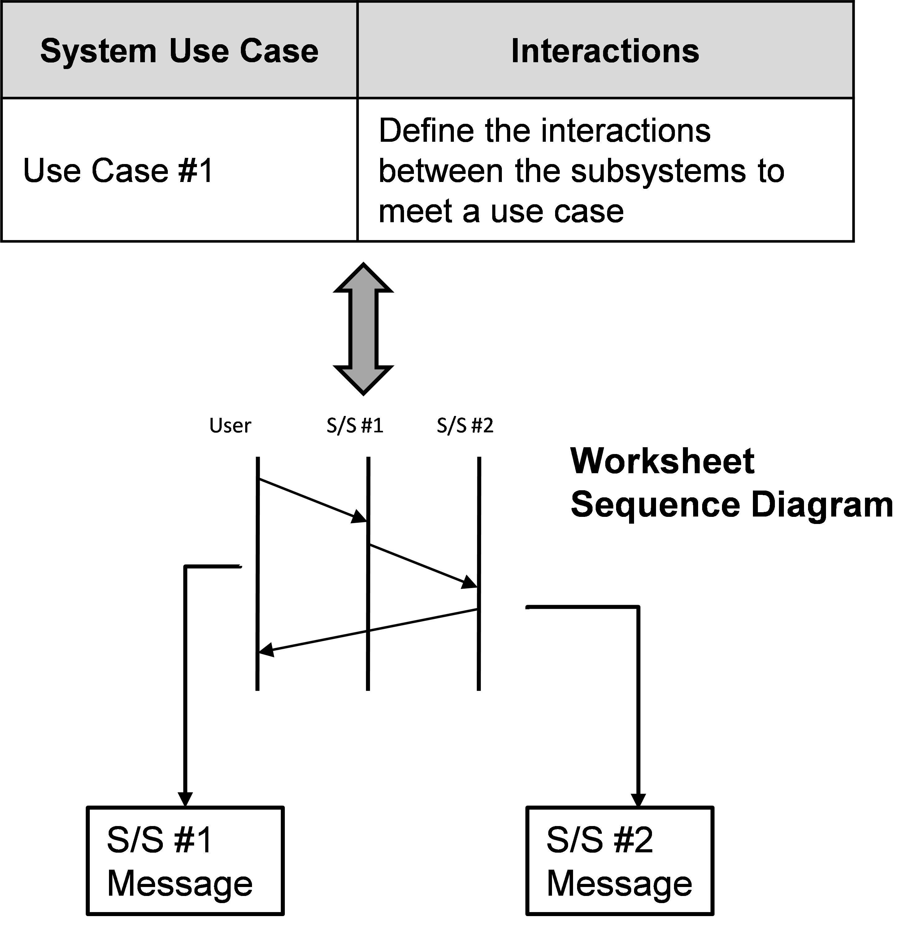
The workflow diagram, based upon the internal interface requirements and the preliminary analysis during the concept elaboration format show the interactions between subsystems.
After analysis of the workflow determined that service timings, the time that a subsystem has to respond to (service) a message identified in the workflow diagram, need to be developed. A transfer function approach to the determination of service timing during this step identifies the total service time for a use case. This transfer function details the timing as follows

The formula above uses the concept of early start versus late start timing from the concepts associated PERT/CPM project scheduling. To determine early and later start timing, the workflow should be constructed as a network, and the critical path can be determined through variations of the timing for the nodes (both message timing and service timing are considered nodes). Variation in the finish time can be found as

The following figure shows how the network analysis for a workflow can be structured

Many project scheduling programs can perform the calculations shown above, and the use of this tool provides simple way to develop the timing parameters for a workflow
Minimum event timing should also be considered, but this analysis is more heuristic. From the analysis of the network by varying the minimum duration of an event, event timings that occur well ahead of other events can be identified. In this situation, limiting or delaying the event can be considered.
In this example, a final deployment worksheet for this workflow results in a set of complex functional requirements. These requirements rely on the basic workflow diagram as well as a transfer function based upon the PERT/CPM network diagram The following table illustrates the worksheet entries that result from this analysis of a single functional requirement
| Subsystem | Subsystem | System | Deployment | Type | Workflow | Transfer Function |
|---|---|---|---|---|---|---|
| Requirement | Requirement | Diagram | ||||
| Subsystem #2 | Transmit message #1 in 100 to 150 msec | Use Case N | Performance | Performance | Worksheet #2 | Transfer Function #3 |
| Subsystem #1 | Accept Message #1 | Use Case N | Functional | Functional | Worksheet #2 | N/A |
| Subsystem #1 | Process Message #1 in100 to 150 msec | Use Case N | Performance | Performance | Worksheet #2 | Transfer Function #3 |
| Subsystem #1 | Transmit Message #2 | Use Case N | Functional | Functional | Worksheet #2 | N/A |
| Subsystem #1 | Transmit Message #2 in 100 to 150 msec | Use Case N | Functional | Performance | Worksheet #2 | N/A |
| Subsystem #1 | Accept Message #2 | Use Case N | Functional | Functional | Worksheet #2 | N/A |
| Subsystem #2 | Process Message #2 in 200 to 250 msec | Use Case N | Performance | Performance | Worksheet #2 | Transfer Function #3 |
Measurable Performance Requirements
For performance requirement spanning a number of subsystems, worksheet activities involve the development of a formal transfer function. The following figure illustrates the deployment
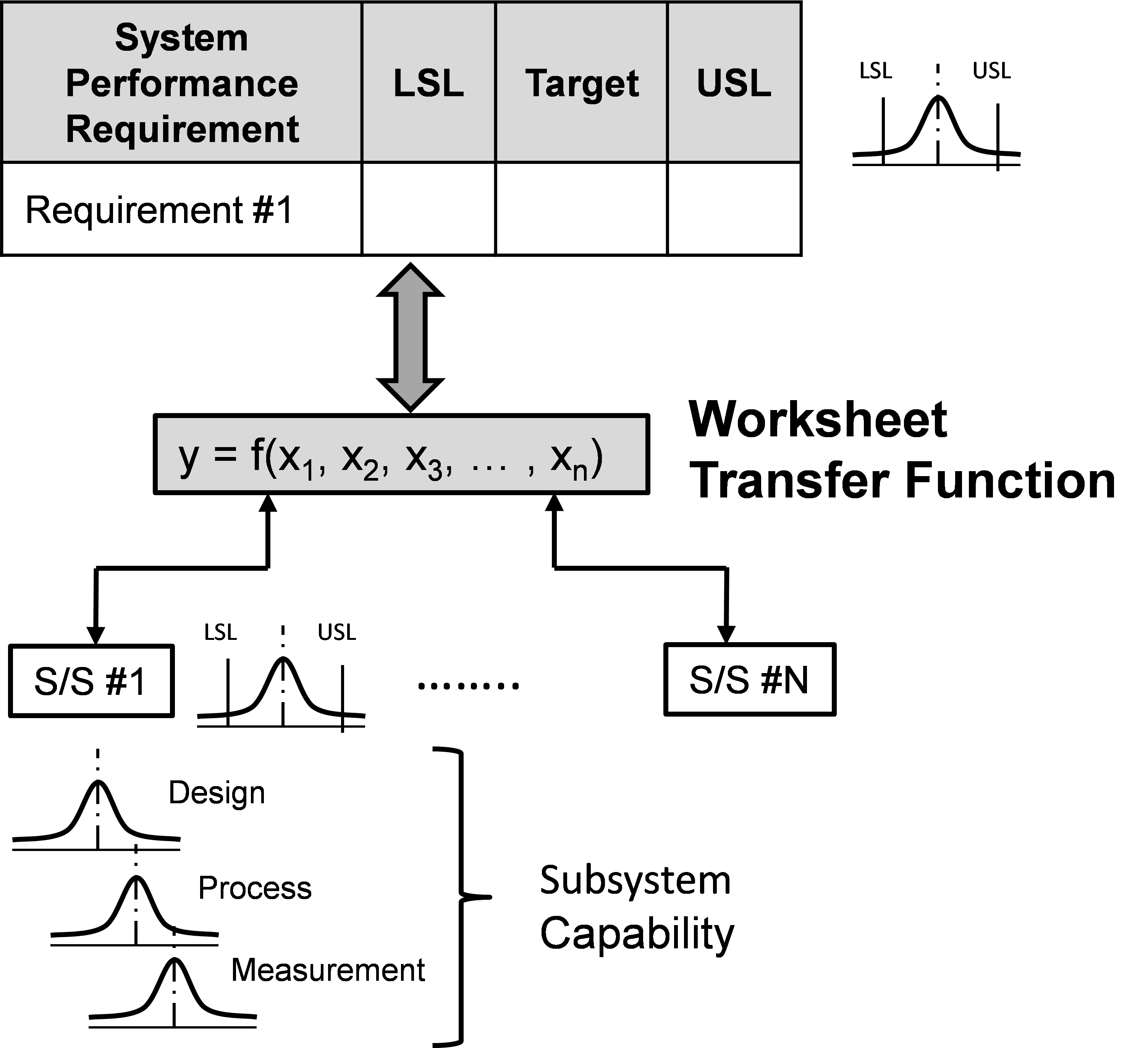
In this situation, the performance requirements is broken down by the formula
The function within the transfer function shows the relationship of the deployed subsystem requirements to the final subsystem requirements.
Performance Transfer functions do not need to be complex. For example, the following transfer function describes the distribution of the system requirement for total weight

Development of a transfer function needs to understand the capabilities of the subsystem, and preliminary tolerance/range allocation should be performed during the development of the development of the transfer function. In this example the design worksheet becomes
| Subsystem | Subsystem | System | Deployment | Type | Workflow | Transfer Function |
|---|---|---|---|---|---|---|
| Requirement | Requirement | Diagram | ||||
| Subsystem #1 | Subsystem Weight will not exceed x kg | Total system weight will not exceed 4kg | Transfer Function | Performance | N/A | Transfer Function #1 |
| Subsystem #2 | Subsystem Weight will not exceed y kg | Total system weight will not exceed 4kg | Transfer Function | Performance | N/A | Transfer Function #1 |
| Subsystem #1 | Subsystem Weight will not exceed z kg | Total system weight will not exceed 4kg | Transfer Function | Performance | N/A | Transfer Function #1 |
After these worksheet related activities, the subsystem requirements have been established and need to be evaluated. The overall worksheet and the complexity of the resulting subsystem requirements should be critically evaluated . At the completion of the worksheet development, the system requirements and architecture have been linked in a set of worksheet entries.