 TGFR Consulting LLC
 Subsystem Decomposition
Decomposition partitions the system into subsystems. Rarely in today’s world does a system of any complexity not have a subsystem-based architecture. Subsystems satisfy several key needs of modern systems
- Parallel Development – with lower coupling comes fewer inter-dependencies and thus more parallel effort can be planned.
- Outsourcing – Subsystem partitioning allow the outsourcing of functionality to groups or organizations with specialized skills
- Fabrication and Manufacturing – manufacturing almost always starts with the build of sub-components. If these sub-components match the subsystems, the development of test methods for manufacturing can be significant lowered
- Post Launch Changes – following release, subsystems allow more structured test and introduction of design changes
As part of the decomposition activity, the decomposing the system to subsystems represents a significant part of the effort. At the system level, the characteristics of the subsystems and interfaces become an important design consideration. Key interface properties are as follows
- Service Granularity – the level of interaction between subsystems. Usually this is defined as either a coarse or fine-grained interface granularity.
- Managed Information – the data structures that are managed by the subsystem and the external visibility of these data structures.
- In-Band versus Out-of-Band Control – the degree to which the interface to a subsystem supports asynchronous out-of-band interactions
The design principle of Service Granularity identifies the optimal scope subsystem interactions. A coarse-grained service operation has broader scope than a fine-grained service, although the terms are relative. The former typically requires increased design complexity but can reduce the number of calls required to complete a task. The four key factors to consider when designing for optimal granularity are performance, message size, transaction and business functionality.
As an example, the interface to a drug delivery pump subsystem may consist of a single, all-encompassing delivery command, with all the delivery parameters, or it may consist of several sequenced commands, where the controller of directly sequences the delivery. The structure chosen will depend upon system considerations, but the direct sequencing will have more granularity and high coupling, which generally places more dependencies on development and testing.
Managed Information refers to the amount of information a subsystem makes available to the rest of the system. In object oriented programming, the data within an object may have a scope of private or public. Generally, public data is kept to a minimum, lowering the coupling between objects. In subsystem decomposition, the minimization and isolation of data signals should be carefully considered to lower the subsystem coupling.
As an example, electrical signals from a pressure sensor used only as part of the delivery function might best be maintained within the delivery subsystem.
Defining the managed information requires identifying the following elements of the data
- The data hierarchy and organization – what data elements are part of what groups. Data elements within a group should usually read or set as a group. A proper hierarchy feeds from and supports the service granularity. The use of database normalization techniques (Microsoft) represents a great way to evaluate data organization and hierarchy.
- The data types – the type of data (enumeration, integer or floating point number) for data elements. The definition of the data type impacts both the “setting” and “getting” of the data. As a rule, unnecessary precision in a data type represents unnecessary coupling between subsystems.
- The data visibility – whether the data is available internally within the subsystem or to connected subsystems significantly impacts overall coupling. “Less is more” is the best approach with visibility.
In-Band versus Out-of-Band control analysis focuses on the degree of asynchronous behavior that the system will support. Out-of-Band control can best be compared to the familiar “interrupt” in computers. With Out-of-Band control, the subsystem or component asynchronously notifies the system of an event and the system schedules the servicing of the event. Alternative approaches using In-Band control use timing loops that regularly poll the various components or subsystems. The choice of In-Band versus Out-of-Band control trades off more subsystem coupling (In-Band) for more complex subsystem design (Out-of-Band).
In analyzing the use of In-Band versus Out-of-Band control, key considerations should be the development of preliminary control flows, the analysis of events and the impact of the event on the control flow. If an event impacts subsequent control operations, Out-of-Band control may be required. As an example, failure of a sensor may require interrupt driven behavior to prevent a control loop from adding invalid data elements to the control loop filter history.
The analysis and definition of the interface characteristics as outlined here drives the scoring of the coupling and cohesion of the system. As architecture evaluation progresses, minimization of the coupling becomes an important measure of the suitability of the architecture. Review of the interface structures during evaluation ensures that the system will have the required performance and coupling characteristics. Once the architecture has been identified, requirements can be mapped to subsystems.
Using Coupling and Cohesion in Decomposition
Considering of the interactions of the subsystem also drives subsystem decomposition. System requirements that depend upon multiple subsystems for fulfillment are not as desirable as those that can be satisfied by a single subsystem.
As part of the decomposition process, a preliminary set of system requirements should be put in place, based upon the CTQs, VOB and risk analysis. Following the decomposition to subsystems, these requirements can be evaluated as for interaction against the subsystems. The following shows the structure of this evaluation

This evaluation strives to establish a subsystem breakdown with minimal interaction. A perfect mapping results in a system with far too many subsystems, whereas a system with a high degree of interaction between subsystems impacts integration and verification.
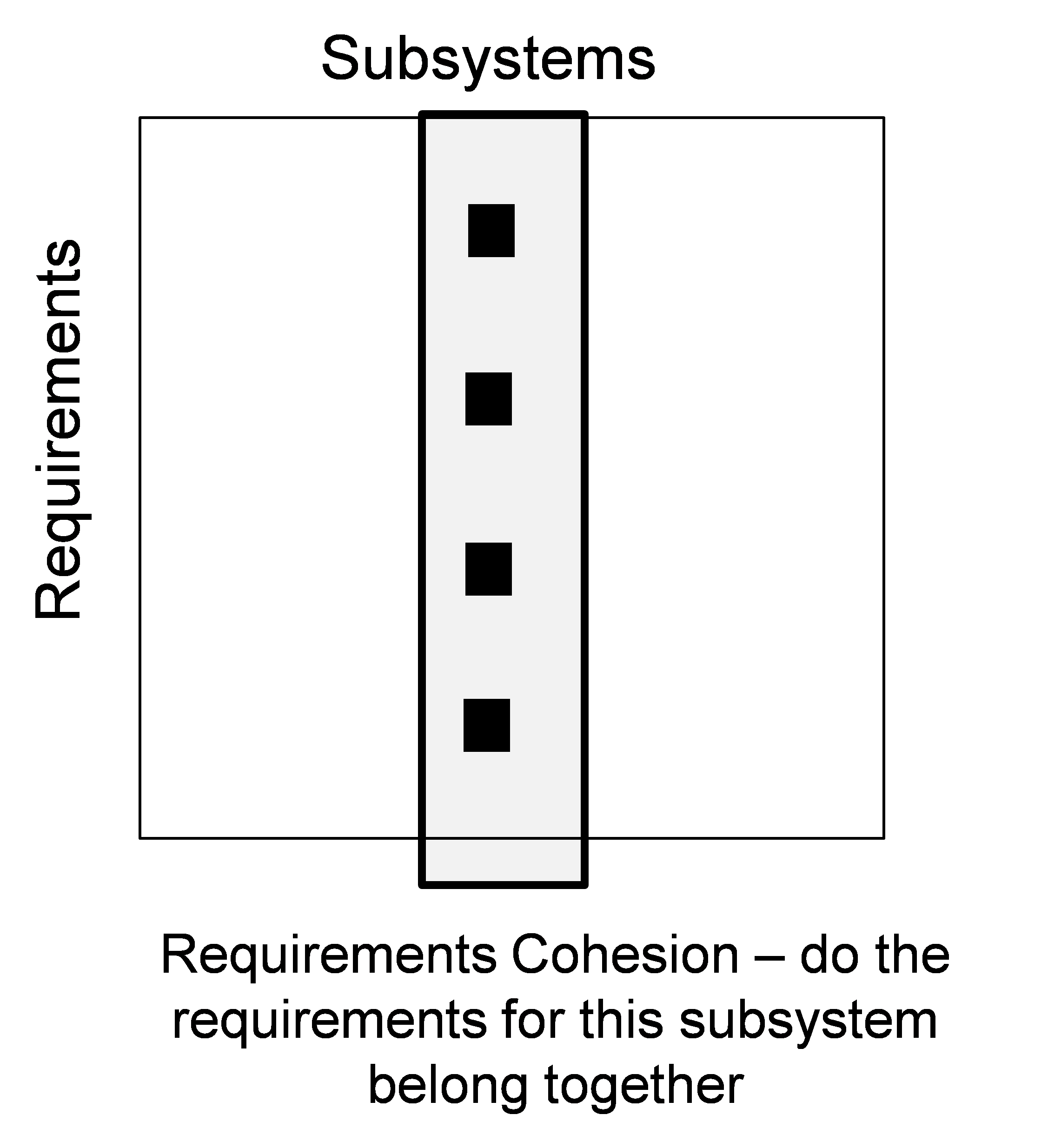
In addition to the interaction, the subsystem mapping needs to consider the subsystem cohesion. Cohesion is the evaluation of the degree to which functionality within the subsystem belongs together. Interaction mapping drives qualitative evaluation of the subsystem decomposition, as shown below
Iterating on the interactions between subsystems and evaluating the cohesion of the resulting mapping should be coupled with the Pugh Matrix and the super concept process. The expectation is that multiple iterations will be required to get the right architecture.
While iterating on the architecture, iteration on the requirements should also take place. The preliminary set of requirements may be subdivided to yield better mapping and cohesion. Often the initial wording of a requirement results in unwanted interaction. By analyzing the cohesion, system and subsystem requirements may be reworded to improve the cohesion. Cohesion with respect to requirements addresses the question
“Do all the statements or needs in the requirements belong together?”
At the end of the process, subsystem decomposition results in requirements that are consistent, and the desired coupling and cohesion has been achieved. The data and analysis from this step will be used to drive further subsystem requirements definitions later in the process.
Structure of a Requirement
The NASA Systems Engineering Handbook defines the following guidelines for requirements
- The requirement is in the form “product ABC shall XYZ.” A requirement must state “The product shall” (do, perform, provide, weigh, or other verb) followed by a description of what must be done.
- The requirement uses consistent terminology to refer to the product and its lower level entities.
- Complete with tolerances for qualitative/performance values (e.g., less than, greater than or equal to, plus or minus, 3 sigma root sum squares).
- Is the requirement free of implementation? (Requirements should state WHAT is needed, NOT HOW to provide it; i.e., state the problem not the solution. Ask, “Why do you need the requirement?” The answer may point to the real requirement.)
- Free of descriptions of operations? (Is this a need the product must satisfy or an activity involving the product? Sentences like “The operator shall…” are almost always operational statements not requirements.)
When reviewing design and development input documents (this often happens in conjunction with the customer), the following criteria should be checked
- Ambiguities and contradictions
- Inconsistent, incomplete or unfeasible information or requirements,
- Unrealistic performance specifications,
- Requirements that cannot be verified or validated,
- Unstated or assumed requirements,
- Inaccurate description of user environment and actions
Verification Check of the Requirements
When requirements have been developed, a key check is to review the verification of the requirement. The general categories of verification are as follows
- Demonstration (D) – The verification on observable functional operation not requiring the use of instrumentation, special test equipment, or subsequent analysis. As an example, the requirement that “all user input shall require separate and explicit user confirmation” can be verified by demonstrating that all input has a confirm screen
- Test (T) – verification using instrumentation or other special test equipment to collect data for later analysis. As an example, test will be required to confirm the accuracy of delivery is +/- 10%
- Analysis (A) – The processing of accumulated data obtained from other qualification methods. Examples are reduction, interpretation, or extrapolation of test results.
- Inspection(I) – The visual examination of design outputs
- Special qualification methods (S) – Any special verification methods, such as special tools, techniques, procedures, facilities, and acceptance limits.
Characterization of verification should be performed during the development of the requirements and analyzed. Requirements that require several types of verification may be poorly written and should be considered suspect.