 TGFR Consulting LLC
 Subsystem Requirements deployment takes the outputs of the worksheet development and makes a more detailed allocation of these entries across the subsystems. The deployment allocates requirement values and tolerances across the mapped subsystems. During development of the design worksheet, each of the functional or performance requirements was considered independently. This may lead to a situation where worksheet activities for different system requirements generated in conflicting subsystem requirements. Subsystem requirements deployment seeks to rationalize the requirements developed in conjunction with the design worksheets and develop a single, consistent set of subsystem requirements.
As an example, at the completion of the workflow analysis, different timing may be assigned to a single message based upon the service timing of different workflows. The following table illustrates the condition
| Subsystem Functional Requirement – Message #1 transmit Time | Timing |
|---|---|
| From Workflow Diagram #1 | 100 -150 msec transmit time |
| From Workflow Diagram #2 | 200 – 250 msec transmit time |
| Consolidated S/S Requirements | 100-150 msec |
The deployment process needs to look carefully at the design worksheet. In many cases, other linked requirements may have an effect, and the change to the subsystem requirement must be carefully considered. In this case, after the review of the workflows, the shorter timing has been adopted, but in another case the longer timing might be a better choice and other requirements adjusted instead. The workflow and network diagrams are critical tools in the deployment process.
For a performance requirement, the process may consider the lower and upper spec limits in addition to the target values. In following example of weight, the consideration of the upper and lower specification limits resulted in tightening the overall range of variation allowed and to accommodate the requirements of the different worksheets.
| Subsystem Performance Requirement – System Weight | LSL | Target | USL |
|---|---|---|---|
| From design worksheet #1 | 3.1 | 3.3 | 4.0 |
| From design worksheet #2 | 2.8 | 3.1 | 3.5 |
| Consistent S/S requirement | 3.1 | 3.3 | 3.5 |
The N2 Chart
Following the completion of the initial subsystem requirements deployment, the final step confirms both the subsystem partitioning and the requirements allocation using an N2 chart . Robert Lano of TRW conceived the N2 chart in 1977, and this concept has been modified and implemented in many different forms, but the key principle is to visually represent the interactions between subsystems
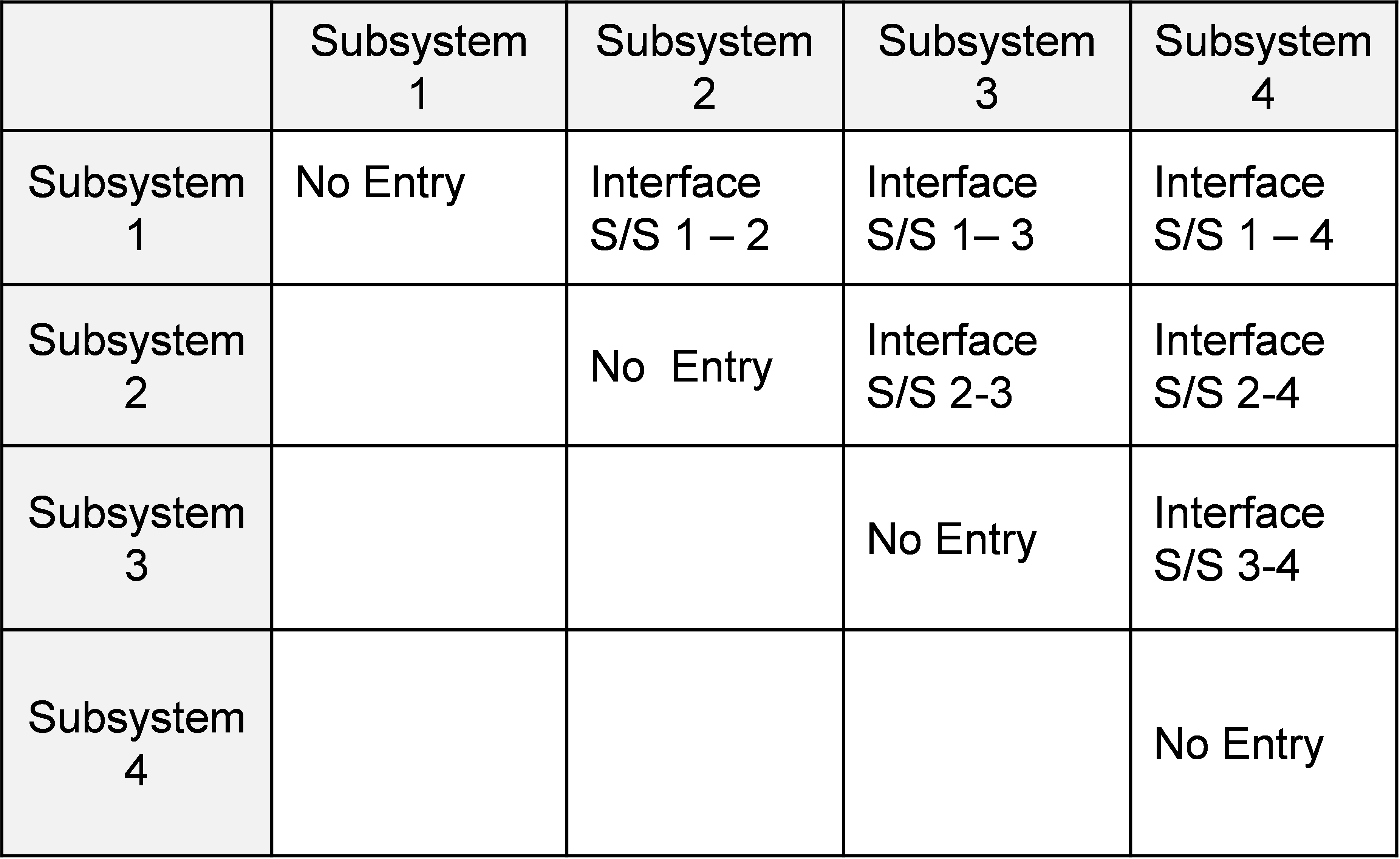
The N2 chart represents another sort of the design worksheet. By sorting by the worksheets and the deployment tables, the information on the coupling of the subsystems can be easily developed.
Requirements Deployment Outputs
The Design Worksheet and the subsystem requirements tables provide information for use throughout the development lifecycle. Specifically, this information provides
- The mapping of how the subsystem requirements fulfill the system requirements
- The interrelationship between the subsystem for each system requirement (through the workflow diagrams, transfer functions and the N2 chart)
- The rationale for allocations of the requirements
- Completeness for the partitioning of the subsystem requirements
While other approaches can drive similar capability, the design worksheet consolidates information on deployment into a single location, providing a structure for search and analysis capability. Subsystem requirements are just a filter on the design worksheet for the subsystem. Traceability is easily derived from the design worksheet.
It should be noted that the size of a design worksheet often requires the use of a special tool. Sometimes, the use of a simple relational database such as Microsoft Access will be sufficient, and sometimes the scope will require the integration into an advanced lifecycle management tool.